




A practical path from a box of parts to your first successful boot.
Reviewed October 8, 2026 · Build Guides · U.S. edition
You have the parts. Now put them together in an order that leaves room to work, makes the cables easier to reach, and gives you a clear checkpoint before installing Windows.
This guide follows a new, standard-layout AM5 gaming tower with DDR5 memory, an M.2 NVMe SSD, an air cooler, and a separate graphics card. Intel builds, reverse-connector boards, and liquid coolers need their own mounting instructions. Keep the manuals for your exact parts open as you work.
Before you start
Clear a sturdy table and use a clean, nonconductive work surface. Set out a Phillips screwdriver, a small screw tray, cable ties, and the mounting hardware supplied with the case and cooler. Some parts use a different screwdriver bit; check before starting. Keep drinks away from the work area. MSI preparation guide.
Keep the PSU switched off and its AC cord unplugged while assembling or reseating components. Handle boards and memory by their edges. Use appropriate ESD precautions, such as a properly connected ESD wrist strap, and avoid working on carpet. Crucial installation guidance.
Before opening the CPU socket, confirm the board supports your CPU and its required BIOS version, the memory is the correct type, and the case has room for the cooler and GPU. Save packaging, serial numbers, and U.S. retailer receipts until the build is working. Compatibility checks belong before assembly; return windows vary by store.
The build order: CPU → RAM → SSD → cooler → motherboard and PSU → cables → GPU → first boot. Read the whole guide once, then return to the step you need.
1. Seat the CPU
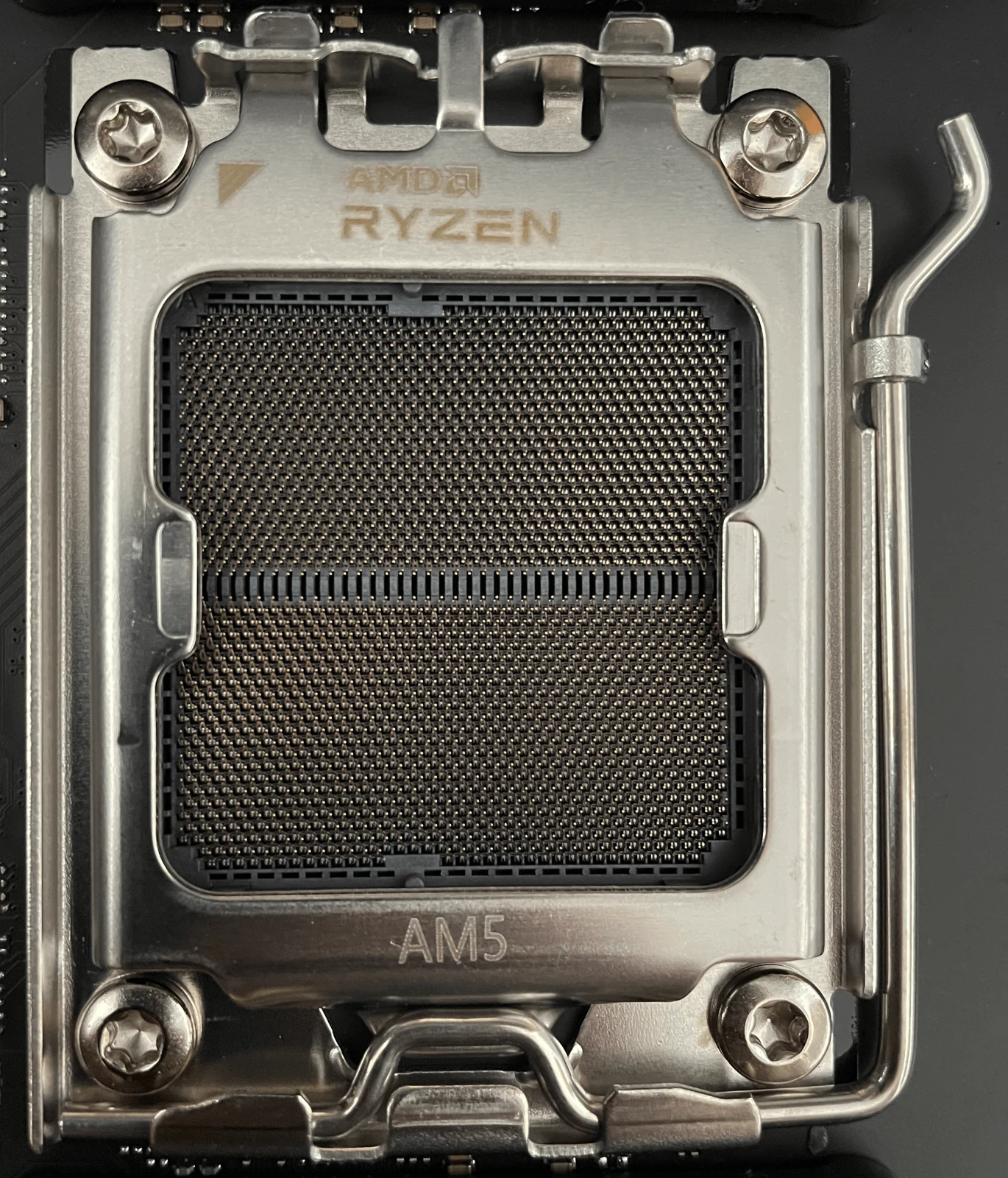
Set the motherboard on its cardboard box or another suitable nonconductive surface. For AM5, release the socket lever and open the retention frame. Hold the CPU by its edges, align its triangle with the socket's orientation mark, and lower it straight into position. It should sit flat without being pushed into place. AMD AM5 installation instructions.
Close and latch the frame according to the board's manual. Follow its instructions for the protective socket cover, and save that cover with the packaging. Never touch the socket contacts or remove the socket mechanism to install the processor. If the CPU does not sit correctly, stop and recheck its orientation before closing the frame. MSI AM5 socket guidance.
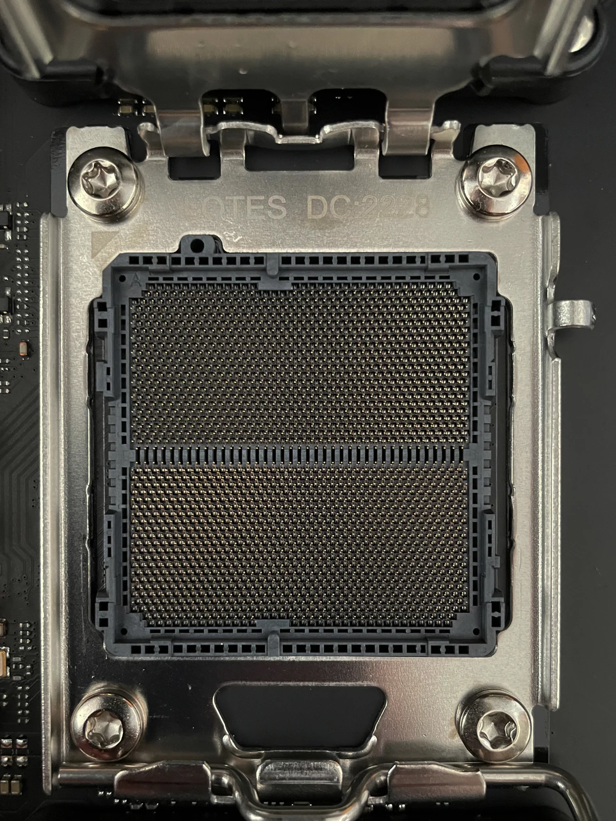

Checkpoint: The CPU sits flat and the retention lever is secured. Do not power the system until its cooler is installed.
2. Install the memory
Use the slot order in your motherboard manual. For example, MSI's MAG B850 TOMAHAWK MAX WIFI specifies DIMMA2 and DIMMB2 for a two-module kit: the second and fourth slots counting outward from the CPU. That example is not a substitute for checking another board. MSI memory layout.
Open the movable latches, align each module's offset notch with the slot, and press straight down with even pressure until it is seated and the latches engage. Keep your fingers off the gold contacts. If it will not seat, recheck the notch and latch position. Crucial memory installation.
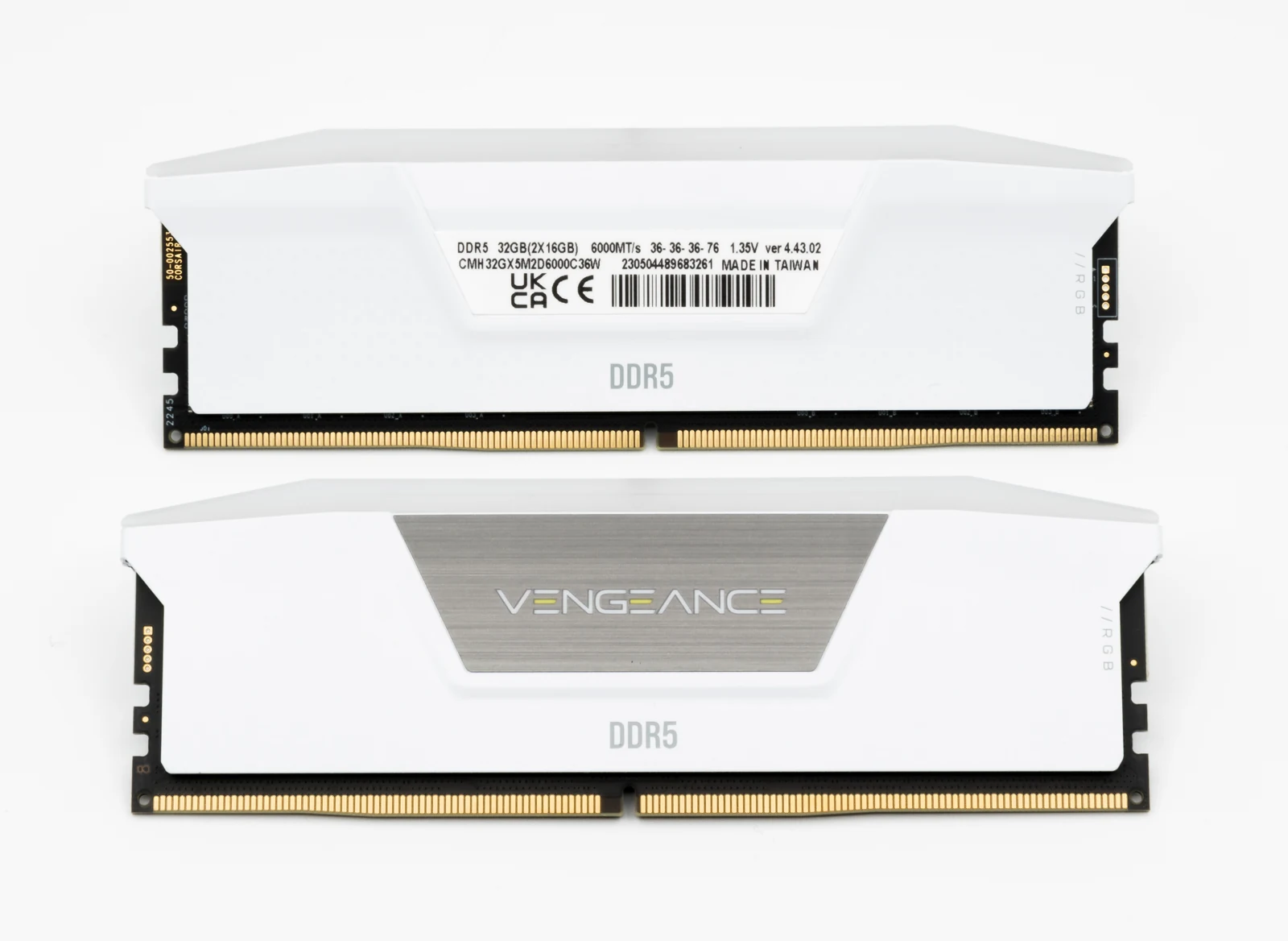

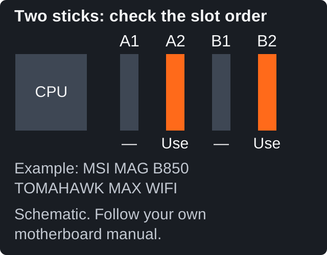
Checkpoint: Both modules sit at the same height and their retaining latches are engaged.
3. Install the M.2 SSD
Find the board's recommended slot for your boot SSD. Match its interface and length; an M.2 2280 drive needs the 2280 mounting position. Check whether using that slot shares lanes or disables another connector before adding multiple drives.
Remove the slot's heatsink if present, then follow the board's screw or tool-free latch procedure. Insert the SSD at the specified angle, lower it to the mounting point, and secure it without overtightening. Remove the protective film from the heatsink's thermal pad before reinstalling the heatsink. MSI M.2 installation example.
Do not confuse the pad's protective film with the SSD's factory label or heat spreader. Follow the SSD maker's instructions; Kingston, for example, specifies placing an added heatsink over the Renegade G5's existing heat spreader. Kingston SSD guidance.
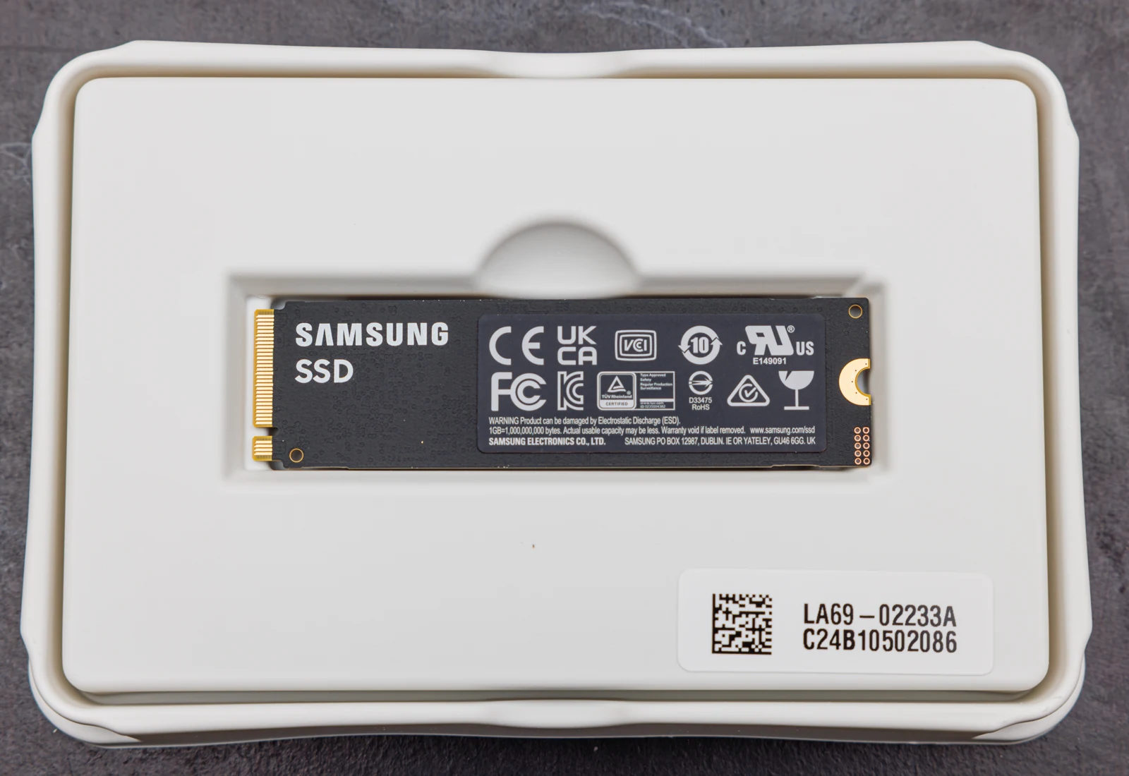

Checkpoint: The drive is secured and the heatsink is back in place, if required.
4. Mount the CPU cooler
Use the cooler's AM5 mounting parts and its own installation sequence. Many AM5 air coolers retain the motherboard's stock metal backplate. Noctua's NH-D15 G2, for example, removes the stock cooler brackets while keeping that backplate in place. Do not transfer an Intel mounting procedure to AM5. Noctua AM5 instructions.
Remove any protective film from the cooler's contact plate. Check for pre-applied thermal paste; otherwise apply the paste using the cooler or paste manufacturer's recommended amount and pattern. Tighten the mounting screws evenly, following the specified sequence, and connect the fan to the CPU fan header. MSI cooler installation overview.
Check RAM clearance and the case's side-panel clearance before finalizing fan position. Raising a tower cooler's front fan to clear tall memory also increases its total height. Noctua clearance guidance.
Checkpoint: The cooler is secure, its contact surface has no protective film, and its fan cable is connected.
5. Install the motherboard and PSU
Remove the case panels and check the standoffs against your motherboard's mounting holes. Remove any extra standoff that would touch the underside of the board where there is no mounting hole; that can damage the board. MSI standoff warning.
If the board has a separate I/O shield, install it first. Lower the board into place, align it with the standoffs, and secure it with the case's motherboard screws. Use the correct screws from the accessory bag. CORSAIR case installation example.
Mount the PSU using the case's instructions for its position, ventilation, and screws. Attach the modular cables you need before sliding it in if access will be tight. Use the cables supplied with that PSU, or replacements explicitly approved for its exact model. Modular cables are not universal—even within one brand. CORSAIR cable compatibility.
Checkpoint: The board and PSU are firmly mounted, and no loose screw remains inside the case.
6. Connect power, case cables, and fans
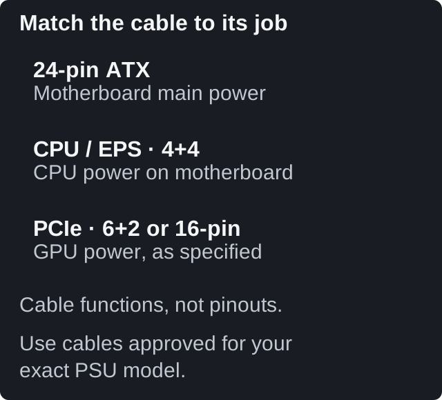
Connect the motherboard's 24-pin power cable and the CPU/EPS power cables required by its manual. The CPU cable is typically labeled CPU or EPS and may split into 4+4 pins. A GPU cable may split into 6+2 pins. They serve different connections; use the labels and documentation rather than trying to make one fit. CORSAIR PSU installation.
Find the front-panel header diagram for your board. Connect POWER SW, then any reset switch and indicator LEDs. Observe the LED polarity shown in the manual. Connect HD AUDIO, front USB, and front USB-C to their matching headers. Some cases combine front-panel connectors; check compatibility before plugging in the block. CORSAIR front I/O guidance.
Connect case fans to suitable fan headers or their supplied hub. Follow the hub's instructions for any separate power connection. Lighting and fan motor power may use different cables. A standard 5V three-pin ARGB connector must not go onto a 12V four-pin RGB header. CORSAIR ARGB and RGB guidance.
Checkpoint: Power connectors are fully seated, the case power switch is connected, and cables cannot enter fan blades. Finish cable ties after confirming the system boots.
7. Install and power the graphics card
Use the PCIe slot recommended for the main graphics card, usually the upper full-length slot. Remove the case slot covers the card needs, release the slot's retention mechanism as instructed, and seat the card squarely. Secure its rear bracket and install its support bracket if supplied. MSI GPU installation overview.
Connect every power plug required by the exact card. Cards with eight-pin sockets and cards with a 16-pin connector have different cable requirements. Use an approved cable or the supplied adapter as directed; do not leave an adapter's required input unconnected.
For a 16-pin connection, confirm full insertion and latch engagement before routing the cable. Leave enough room for the connector and cable so the side panel does not push on them. Check your card's own clearance requirements: NVIDIA's RTX 5080 Founders Edition guidance reserves additional space for the power cable, while partner-card dimensions vary. NVIDIA installation requirements.
Checkpoint: The card is secured, supported as needed, and fully connected to power.
8. Run the final physical check
Before connecting AC power, pause for one complete inspection:
- CPU cooler mounted; CPU fan cable connected.
- Memory and SSD secured; cooler and heatsink protective films removed where required.
- Motherboard, CPU, and GPU power connected with the correct cables.
- Case power switch connected to the correct header.
- No loose screws, unused standoffs beneath the board, or cables in fan blades.
- GPU power connector has clearance from the side panel.
These checkpoints bring together the manufacturer instructions above. A clean inspection is easier while the side panels are still off.
9. Power on and enter BIOS
Connect the monitor to the graphics card's HDMI or DisplayPort output for this discrete-GPU build, then connect a keyboard. Select the matching input on the monitor. Connect the PSU's AC cord, set its rear switch to I, and press the case power button. ASUS display and power troubleshooting.
The first start can take longer while memory is trained. Give the board time to complete its process instead of repeatedly switching it off. The duration varies by board, firmware, and memory configuration; use the manufacturer's guidance rather than a universal countdown. ASUS memory-training guidance.
Enter BIOS using the key specified for your motherboard, such as Delete. Confirm that it detects the CPU, the full installed RAM capacity, and the SSD. Check the CPU temperature and fan reading; if the temperature rises rapidly or the CPU fan is not running, shut down and recheck the cooler installation before proceeding.
Leave memory overclocking profiles off for this initial check. A DDR5-6000 kit can first run at the platform's default JEDEC settings; the box's advertised profile speed is not necessarily the first-boot speed. Enable EXPO or XMP later, after establishing a working baseline. MSI's current memory-profile guide.
Checkpoint: BIOS opens and recognizes the expected hardware. You are ready for operating-system installation; assembly alone does not install Windows or drivers.
If the first boot does not work
If nothing powers on, check the AC connection, PSU switch, motherboard and CPU power, and case power-switch connection. If the fans run but there is no picture, check the monitor input and GPU output, then allow memory training to finish. Switch off and unplug the PC before reseating parts. ASUS troubleshooting.
If a diagnostic light stays on, use your board's manual to identify it. Record the light label or code before changing anything. A new drive without an operating system has nothing to boot yet; check whether BIOS detects it before treating a boot-device warning as a failed assembly.
Change one thing at a time. That gives you a useful answer when a correction works. Keep the first successful BIOS screen as your milestone, then move on to installing Windows, motherboard drivers, and the graphics driver.